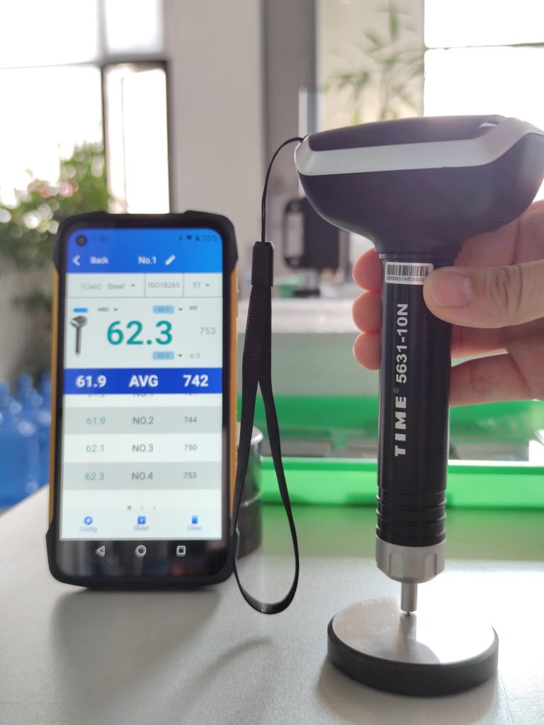
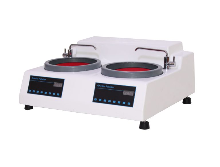
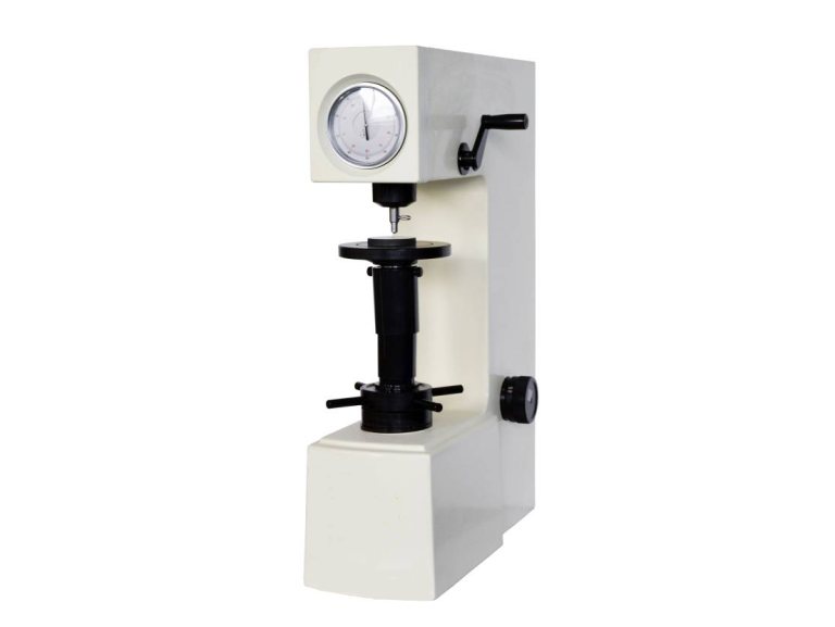
The microhardness tester is a high-tech product that integrates optical, mechanical and electrical components. The hardness tester has a novel shape and has good reliability, operability and repeatability. It is an ideal product for testing microhardness.
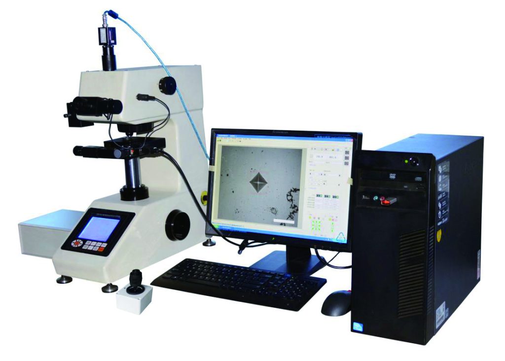
Using C language programming, high-magnification optical measurement system and optical dual-channel structure, new technologies such as photoelectric and photocouple sensing. Through key operation, the length of the measured indentation can be input on the keys, and the hardness value, conversion scale, test force, test force holding time and number of measurements can be displayed on the LCD screen.
It can also be configured according to the user’s special needs, and can take pictures of the measured indentation and material metallographic structure, a video measurement device and an automatic indentation measurement device, as well as the measurement of Knoop hardness.
- Sample
1) The surface must be clean. If the surface is stained with grease and dirt, it will affect the measurement accuracy. When cleaning the sample, alcohol or ether can be used to wipe it;
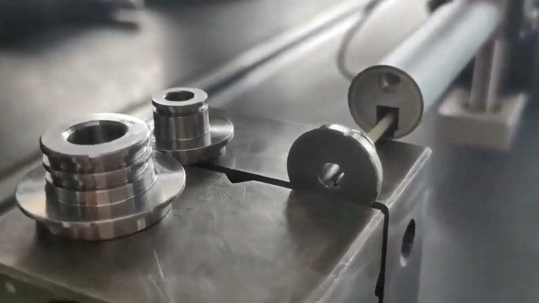
2) When the sample is a filament, sheet or small piece, it can be clamped with a filament clamping table, a sheet clamping table and a flat mouth clamping table respectively, and placed on the cross test bench for testing; if the sample is very small, If it is too small to be clamped, the test piece will be mounted and polished before testing;
3) To ensure the accuracy of the test, the thickness of the sample must be ensured. According to national standards, the thickness of the test piece must be no less than 8 to 10 times the indentation depth. Several methods are provided below to determine whether the thickness meets the regulations.
[Direct observation method]
Test the specimen in accordance with the specified requirements. After the test is completed, observe whether there are traces of deformation on the edge and back (supporting surface) of the specimen. If traces appear, the test results are invalid. It means that the thickness of the test piece is too thin to meet the test requirements. At this time, there are two options. One is to redo the test piece. Some parts cannot be changed. The second is to choose a smaller test force, which can only be done within the specified requirements.
[Formula calculation method]
The calculation formula for the thickness of Vickers hardness test piece: h≈d/7.
[Look-up table method]
Available tables: Sample minimum thickness and detection force selection table - Eyepiece
1) Due to the parallax of each person, the reticle in the field of view of the micrometer eyepiece may be blurred. Therefore, when changing observers, the eyecup on the eyepiece should be slightly rotated to make the reticle in the field of view clear;
2) Insert the micrometer eyepiece into the eyepiece tube. Pay attention to insert it to the bottom without leaving any gap, otherwise it will affect the accuracy of the measurement. When measuring the diagonal of the indentation, you must measure its vertex, then turn it 90° and then Measure another pair of vertices;
3) The zero point must be reset every time the machine is turned on. - Select test force and indentation size
When measuring Vickers hardness, as long as the conditions of the specimen permit, try to use a large test force, and the measurement will be relatively accurate. Generally, hard materials use a larger test force; soft materials use a smaller test force.
According to custom, it is most convenient to measure when the diagonal length of the indentation is about 50um, but the thickness of the material must also be considered.
Reference: Material thickness ≥1.5×indentation diagonal length.
For example: material thickness = 0.1mm, then the diagonal length of the indentation cannot be greater than 0.066mm. Here it satisfies: 0.1≥1.5×0.066

